

Conveyor belt systems are central to modern production lines, yet the question of how they actually work is often harder to answer than expected. Most people recognize the moving surface — but the real question is how all the components around that surface cooperate to keep products moving continuously, reliably, and in the right direction.
A conveyor belt system works by converting motor-driven rotation into continuous linear movement of a carrying surface1 — whether that surface is a flat belt, modular plastic belt, or chain plate. Supporting structures keep the surface stable, tensioning components maintain tracking, guides control product path, and a control system regulates the entire operation. Each component plays a distinct functional role.
Understanding the system at a component level matters more than most buyers initially expect. When a line stops or a part wears out, the team that can describe which function failed — not just "the belt is broken" — finds the right replacement faster and communicates more effectively with suppliers.
What Are the Core Components of a Conveyor Belt System?
Many production teams can name individual conveyor parts, but find it harder to describe what each one actually does in the system. That gap leads to mismatched replacements and unclear supplier communication.
In most conveyor belt systems, six functional groups work together: the drive unit, the carrying surface, the support structure, the tensioning system, the guiding and containment components, and the control system. Each group performs a different role, and a problem in any one group affects the whole line.
Understanding these groups gives you a working model of the system — not just a parts list. Here is how each functional group contributes.
The Drive Unit: Where Movement Begins
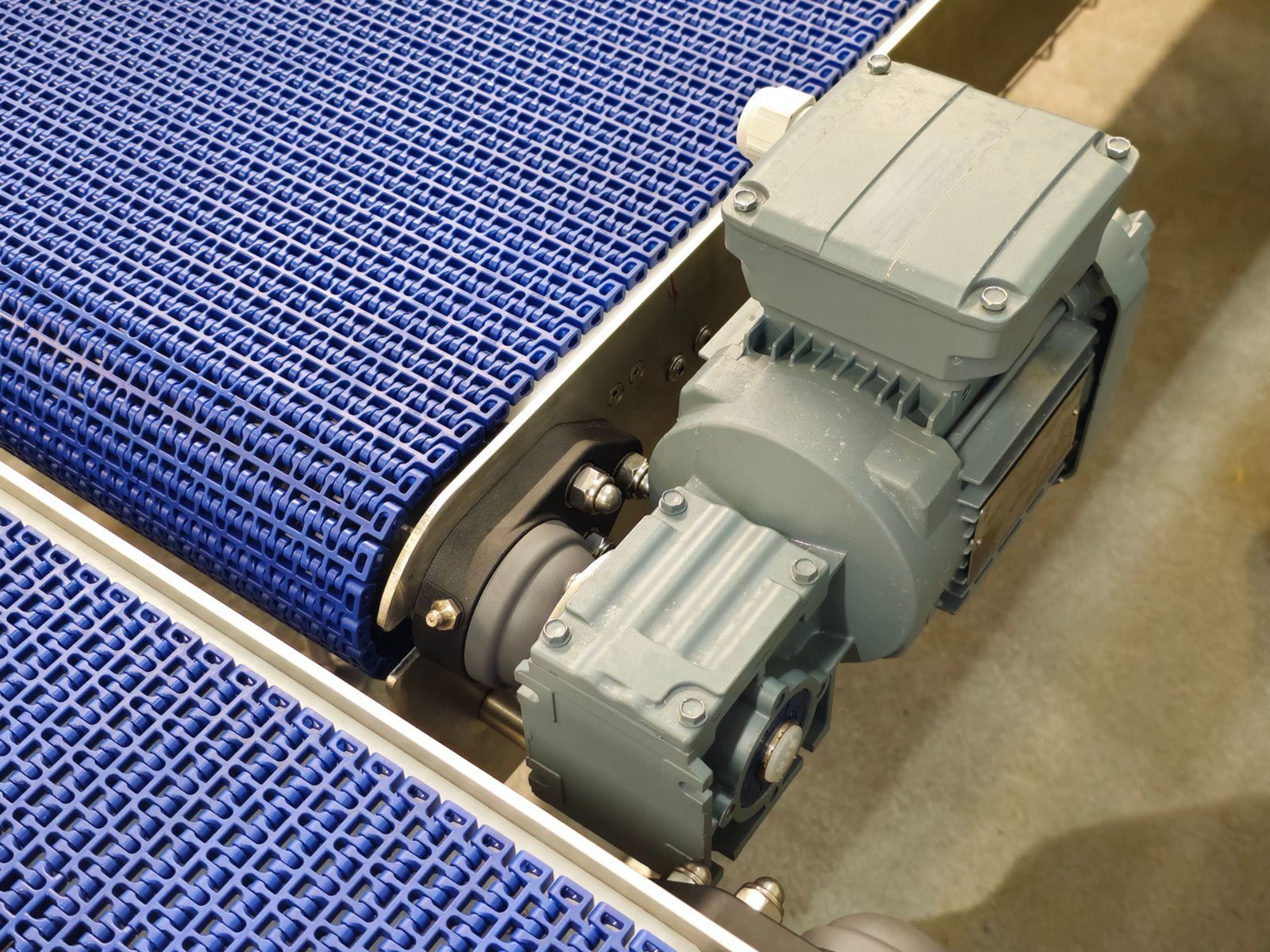
The motor is the system's power source, but it does not drive the belt directly. In most configurations, the motor connects to a gearbox or reducer, which adjusts output speed and increases torque2. That output then turns a drive sprocket or drive pulley, which engages the carrying surface and pulls it forward.
The drive unit's placement affects the entire system:
- Head drive (motor at the discharge end) is the most common arrangement. The belt is pulled under tension, which keeps tracking stable.
- Center drive configurations exist on longer conveyors where distributing the load makes more sense.
- Multiple drives appear on high-load or inclined systems.
In chain plate conveyors and modular belt conveyors, the drive sprocket teeth engage directly with the links or modules. In flat belt conveyors, friction between the pulley surface and the belt underside transmits the driving force. These are mechanically different engagement methods, but the functional logic — rotating drive component transfers motion to carrying surface — is the same across all three types.
The Carrying Surface: Belt, Modular Belt, or Chain Plate
The carrying surface is what most people picture when they hear "conveyor belt system." But the surface type determines far more than just appearance — it affects cleaning behavior, product handling, permitted loads, and which support components the system uses.
| Carrying Surface | Engagement Method | Typical Support | Common Applications |
|---|---|---|---|
| Flat belt | Friction on drive pulley | Slider bed or rollers | General assembly, packaging, light food |
| Modular plastic belt | Sprocket-tooth engagement | Wear strips or rollers | Food processing, washdown environments |
| Chain plate (slat chain) | Sprocket-tooth engagement | Guide rails and wear strips | Canning, bottling, heavy product handling |
In practice, modular belts and chain plates are often more relevant in food, beverage, and industrial manufacturing environments — which is the context we encounter most often in supplier discussions with factories and maintenance teams.
How Does Tension Keep the Belt Tracking Correctly?
A moving belt under no tension would drift, slip, or sag within seconds. Tension control is one of the least visible functions in a conveyor belt system, but one of the most consequential when it fails.
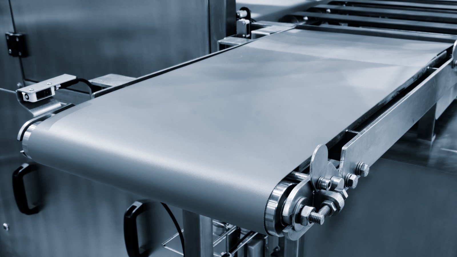
In most conveyor belt systems, a tensioning device — typically a take-up pulley or adjustable tail end — applies controlled pulling force on the return side of the belt. This keeps the belt taut enough to maintain contact with the drive pulley, prevents sagging between support points, and helps the belt track straight.
Why Correct Tension Matters
Too little tension causes:
- Belt slippage on the drive pulley
- Tracking drift to one side
- Premature wear on belt edges and return rollers
Too much tension causes:
- Excessive load on bearings and shafts
- Accelerated belt fatigue and elongation
- Higher energy consumption
Tensioning Methods in Practice
Screw take-up is the most common method on shorter conveyors. The tail pulley is adjusted manually using threaded bolts. This is simple and inexpensive, but requires periodic manual re-tensioning as the belt stretches over time.
Gravity take-up uses a weighted carriage on the return side. The weight applies constant tension automatically, compensating for belt elongation without manual intervention. This is more common on longer or higher-load systems.
Spring-loaded take-up is a compact variation used when space is limited.
For modular belts and chain plate conveyors, tension management works somewhat differently. Because these surfaces are dimensionally stable and engage sprockets positively, the system relies more on sprocket positioning and belt path geometry than on continuous tensioning force. However, proper initial tension and correct sprocket alignment still matter significantly to tracking behavior.
What Supports the Belt Along Its Travel Path?
Between the drive end and the tail end, the carrying surface needs continuous support to maintain a flat, stable product-carrying plane. Without adequate support, belts sag, products shift, and wear accelerates.
In flat belt conveyors, the two main support approaches are slider beds and carrying rollers. Slider beds provide a solid, continuous surface — better for light, small, or irregularly shaped products. Carrying rollers reduce friction and are better suited for heavier loads. The return side of the belt typically runs on return rollers or a flat return pan.
In modular belt and chain plate conveyors, the support structure is different:
- Wear strips made from low-friction plastic (commonly UHMW-PE or similar materials) run along the underside of the belt. The belt slides over these strips.
- Guide rails on the sides contain the belt laterally and prevent it from riding off the support structure.
- Some systems use a combination of wear strips and rollers depending on load distribution requirements.
Wear Strips: A Component Worth Understanding
From a component supply perspective, wear strips are one of the most frequently replaced parts in modular belt and chain plate conveyor systems. They are not structural, but they directly affect:
- Belt running resistance — worn strips increase drag and load on the drive motor
- Belt and chain life — a worn or uneven strip surface accelerates underside wear on the belt itself
- Hygiene compliance — cracked or degraded strips in food processing environments create contamination risks
Wear strip material selection depends on belt speed, product load, operating temperature, and cleaning chemical compatibility. These are decisions better made in consultation with the equipment or component supplier than by substituting the nearest available material.
How Do Guides and Side Guards Control Product Flow?
Moving products do not always stay centered on their own. On inclined sections, curves, or high-speed lines, products shift, rotate, or topple without some form of lateral containment.
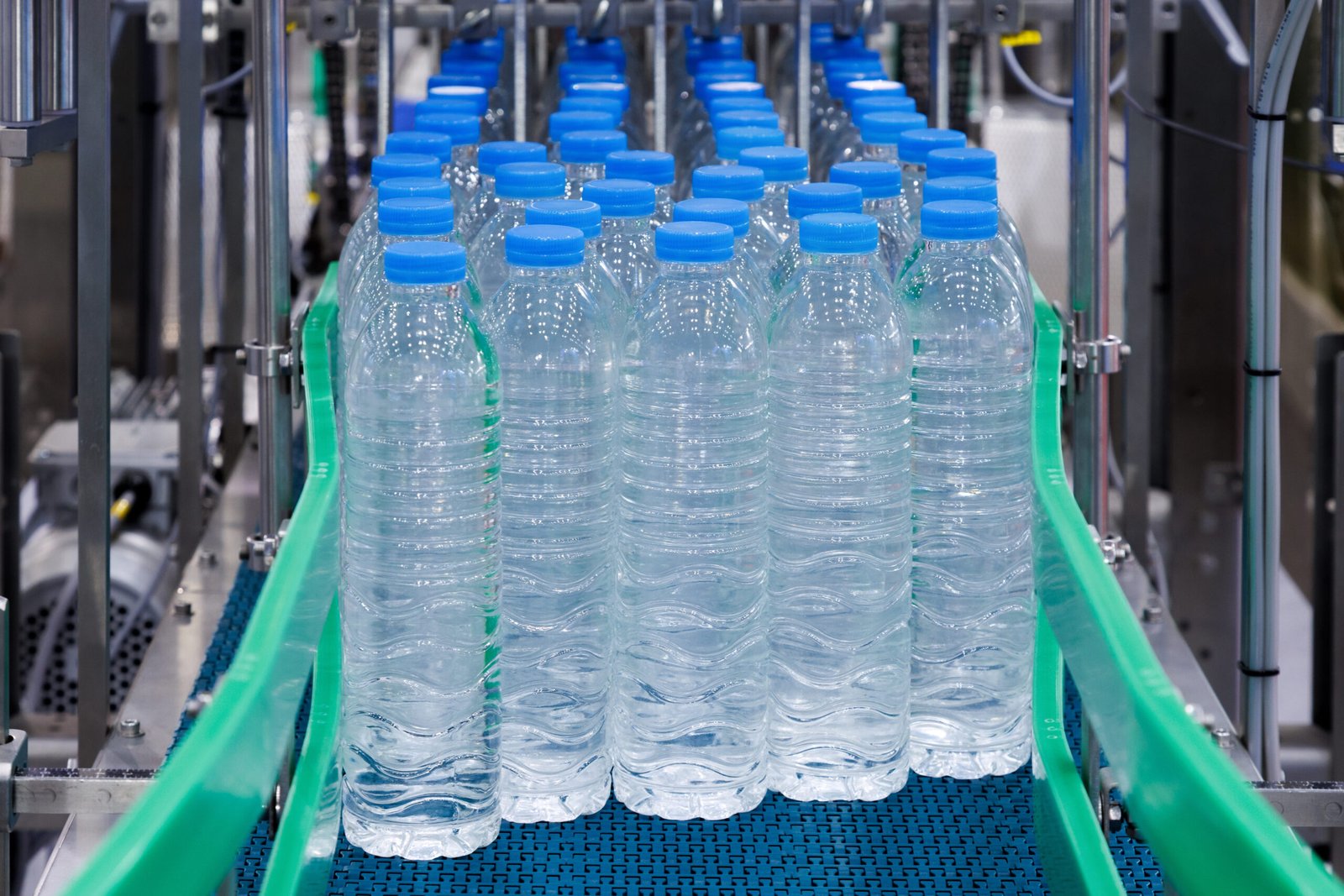
Guide rails and side guards are the components that define and maintain the product path. They function independently from belt tracking guides — their job is controlling products, not the belt itself.
Functional Roles of Guiding Components
- Side guards (also called sideboards) enclose the belt laterally to prevent product from falling off the conveyor edge. In food and pharmaceutical environments, hygienic side guard designs with smooth surfaces and minimal crevices are standard.
- Guide rails positioned above the belt surface direct product into lanes, hold upright containers in position, or channel products into a specific orientation for the next process step.
- Lane dividers on wider conveyors split a single product stream into multiple lanes for downstream equipment.
The material and adjustability of guide rails matters practically:
| Guide Rail Type | Material | Adjustment | Best Suited For |
|---|---|---|---|
| Fixed steel rail | Stainless steel | None or limited | High-load, stable product runs |
| Adjustable polymer rail | UHMW-PE, HDPE | Lateral position adjustable | Changeover lines, mixed formats |
| Flexible rail with brackets | Various | Height and angle adjustable | Inclined or curved sections |
In manufacturing environments where product formats change regularly, adjustable guide rail systems reduce changeover time considerably.
How Does the Control System Regulate Conveyor Operation?
The drive, belt, and support structure create the mechanical system. The control system tells that mechanical system when to run, at what speed, and how to respond to upstream or downstream conditions.
At minimum, a conveyor belt system control includes a motor starter, stop/start controls, and basic safety interlocks. More integrated systems include variable frequency drives (VFDs), speed sensors, and communication interfaces that coordinate multiple conveyors in a production line.
Speed Control and Variable Frequency Drives
Many conveyor systems in food, beverage, and packaging applications use VFDs to adjust belt speed. This matters because:
- Production rates change based on output demand
- Some products require gentle acceleration to avoid toppling or damage
- Downstream equipment (fillers, labelers, packers) may run at variable rates
A VFD allows the motor speed — and therefore belt speed — to be adjusted without mechanical changes.3 From a maintenance perspective, VFDs also extend motor and drive component life by reducing start-up current spikes.4
Safety and Integration
Modern production lines rarely run a single conveyor in isolation. Control systems typically include:
- Emergency stop circuits accessible along the conveyor length
- Belt misalignment sensors that detect tracking problems before they cause damage
- Speed monitoring to detect slip or stoppage
- Integration signals that pause or start individual conveyors based on the state of neighboring equipment
The control system does not change what the belt does — it determines when and how reliably it does it.
Frequently Asked Questions
What is the difference between a conveyor belt and a modular belt conveyor?
A conventional conveyor belt is a continuous flat loop of rubber, PVC, or fabric. A modular belt is constructed from interlocking plastic modules. Modular belts offer better hygienic cleanability, easier section replacement, and positive sprocket drive engagement5 — making them common in food, beverage, and pharmaceutical environments.
Why does a conveyor belt track to one side?
Belt tracking problems are typically caused by uneven tension, misaligned pulleys or sprockets, uneven loading, or wear on the belt edge. Checking pulley alignment and tension distribution first resolves most tracking issues. Persistent tracking problems may indicate a structural frame issue or belt damage.
How often should conveyor wear strips be replaced?
Replacement frequency depends on belt speed, product load, material type, and operating environment. In food processing applications, wear strips are often inspected as part of scheduled maintenance intervals. Visible grooving, cracking, or increased belt running resistance are practical indicators that replacement is due.
Can a single conveyor belt system handle different product sizes?
Yes, within limits. Adjustable guide rails and variable speed control allow many systems to accommodate different product formats. However, belt width, surface type, and support configuration are selected during system design and are not infinitely flexible. Significant product changes may require component modifications.
What causes premature belt or chain plate wear?
Common causes include insufficient or uneven tension, worn or misaligned wear strips and sprockets, foreign material contamination on the belt path, improper cleaning procedures, and running the system outside its designed load or speed range. Identifying which component failed first usually clarifies the root cause.
Conclusion
A conveyor belt system works through the coordinated function of six component groups: the drive unit, the carrying surface, the support structure, the tensioning system, guiding and containment components, and the control system. No single component operates in isolation — each one depends on the others to deliver continuous, stable product movement.
Understanding this system logic helps factories, maintenance teams, and procurement professionals describe problems more precisely, evaluate replacement parts more accurately, and communicate more effectively with component suppliers. At Molytech, we work regularly with manufacturers, distributors, and engineering teams who need accurate component identification and reliable supply. If you are sourcing conveyor components or need help matching parts to your system type, feel free to contact us directly.
"Conveyor belt", https://en.wikipedia.org/wiki/Conveyor_belt. Engineering descriptions of belt conveyors identify the drive pulley or sprocket as the element that converts motor-driven rotary motion into continuous linear movement of the carrying surface. Evidence role: mechanism; source type: education. Supports: A neutral engineering source should explain that belt conveyors use a motor-driven pulley or sprocket to convert rotary motion into linear belt travel.. Scope note: This supports the general operating principle rather than the design of any specific conveyor model. ↩
"optimization of speed reducer gearbox course project ...", https://www.academia.edu/35665347/OPTIMIZATION_OF_SPEED_REDUCER_GEARBOX_COURSE_PROJECT_SUBMITTED_BY_DARSHIT_GOSALIA_ME785_OPTIMIZATION_METHODS_IN_ENGINEERING. Mechanical power-transmission references describe gear reducers as devices that reduce output speed while increasing available torque for driven equipment. Evidence role: mechanism; source type: education. Supports: A mechanical engineering source should support that gear reducers trade rotational speed for increased output torque in drive systems.. Scope note: The source would support the gearbox mechanism generally, not necessarily its prevalence in every conveyor configuration. ↩
"Variable-frequency drive", https://en.wikipedia.org/wiki/Variable-frequency_drive. Energy and electrical-engineering references explain that variable frequency drives regulate AC motor speed by varying the supply frequency, enabling speed adjustment without mechanical drive changes. Evidence role: mechanism; source type: government. Supports: A neutral source should explain that VFDs control AC motor speed by varying the frequency supplied to the motor.. Scope note: This supports the motor-control mechanism; the resulting belt speed relationship assumes a conventional motor-driven conveyor. ↩
"Improving Motor and Drive System Performance - eere.energy.gov", https://www1.eere.energy.gov/manufacturing/tech_assistance/pdfs/motor.pdf. Motor-control references note that variable frequency drives reduce high starting currents and provide controlled acceleration, which can lessen electrical and mechanical stress during start-up. Evidence role: mechanism; source type: government. Supports: A government or engineering source should support that VFDs reduce motor inrush current and can reduce stress during acceleration.. Scope note: This supports a plausible mechanism for longer component life but does not directly prove life extension in every conveyor installation. ↩
"Cleaning Conveyor Belts in the Chicken-Cutting Area of a ...", https://www.academia.edu/92694908/Cleaning_Conveyor_Belts_in_the_Chicken_Cutting_Area_of_a_Poultry_Processing_Plant_with_45_C_Water. Conveyor engineering sources describe modular plastic belts as interlocking module systems driven by sprockets, allowing damaged sections to be replaced and supporting sanitary cleaning practices in appropriate designs. Evidence role: general_support; source type: education. Supports: A neutral conveyor or food-engineering source should support that modular plastic belts use sprocket engagement and can be repaired by replacing modules, with cleanability benefits in sanitary applications.. Scope note: The comparative claim of 'better' cleanability depends on belt design, sanitation procedure, and application conditions. ↩